
The popular adage – “If it ain’t broke, don’t fix it” – might be a piece of advice that is dished out often, but perhaps less appropriate if applied in the context of a manufacturing facility. In the world of mass production, machines are put to repetitive tasks each day to churn out large outputs of identical items. Seeing that production volume is key, it is vital to ensure that machines are often checked for alignment, so that the manufacturing process never gets disrupted.
When the manufacturing process is stopped due to machine misalignment, companies risk losing a significant amount of investment in the form of time delay and scraps. However, these costs can be avoided if companies take careful ownership of preventative maintenance, minimizing the likelihood of equipment failure or downtime drastically.
In fact, by adopting the preventative maintenance approach, quality management departments can also better ensure that products leaving the facility meet quality benchmarks, as well-maintained machines are the foundation of manufacturing processes. Besides, machine alignment significantly increases the lifespan of tools, which can be expensive to replace. For these reasons, companies have found it necessary to perform machine alignment regularly and efficiently.
Single-use tools vs. multi-function device
In the past, companies used to rely on traditional alignment methods that involved tools such as machinist levels, piano or tight wires, and optics (e.g., bore scopes, theodolites, etc.). While these tools worked well in most cases, they often served only single, dedicated function. Using these methods, calibration, and alignment would typically take days or even weeks to complete. It was also common to involve multiple instruments, which translated to higher costs and more time spent on setting up in each step.
Naturally, companies sought out better and faster ways for machine alignment to be done. In the early nineties, the use of laser trackers for industrial measurement became widespread. Compared to traditional methods, the laser tracker is a powerful device that can perform multiple measurement tasks in a much shorter time. By gathering X,Y,Z coordinates with the click of a button.
This device combines the capabilities of several traditional tools in one, including the ability to: check for plumb, level, squareness, and parallelism; verify and conduct positional checks of rotary axes and multi-axis heads; reposition a part on a table without a rotational bed; perform real-time adjustments of machine beds, rails, and ways; as well as measure bore alignment, coupling, and shaft alignment. More importantly, the laser tracker captures data points in a three-dimensional (3D) space, which provides users with higher precision and versatility in data usage.
Basic mechanics of a laser tracker
The laser tracker is a portable coordinate measuring machine (CMM) that is based on 3D coordinate technology. Fundamentally, these devices provide the benefits of CMMs with the added versatility of being portable, which allows the user to deploy wherever there is a need. Designed to handle larger working volumes, laser trackers offer extremely accurate measurements over long ranges. Put simply, a laser tracker establishes the precise location of a target in spherical space by measuring two angles and a distance, each time it takes a measurement. It does so by sending a laser beam to a retro-reflective target, which must be held against the object being measured. The return beam re-enters the laser tracker where the distance to the target can be determined using interferometry or phase shift analysis.
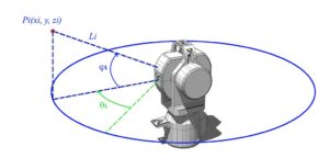
The horizontal and vertical angles to the target probe are determined using precision angular encoders attached to the mechanical axis of a gimbaled beam steering mechanism. Using the two angle measurements and distance determined by the laser, the laser tracker can report the coordinate location of the target probe to extremely high accuracy levels.
In addition, the laser tracker can follow or track the target probe as it moves in real time. This unique feature, coupled with the laser tracker’s ability to internally sample up to 16,000 times per second, enables the user to digitize data on complex surfaces or measure the location of moving objects.
In fact, laser trackers today have impressive measurement ranges and accuracies that provide users with more versatility and better results. For instance, the FARO® Laser Tracker Vantage’s distance measuring range is 80m both ways (160m coverage), and at that range, it captures data at typical accuracies of up to 39 microns (0.039mm / 0.001”). Weighing just under 18kg, the Vantage offers portability and flexibility on measuring large parts, no matter where production is located within the plant. Manufacturers can achieve unprecedented speed and efficiency by capturing more with fewer device moves and shorter routines.
Laser Tracker in Machine Alignment Scenarios
The American Society of Mechanical Engineering established a set of standards for the correct and accepted methods to check and align machine tools with a laser tracker. Here are some documented scenarios of alignment being performed on a variety of machining centers, machinery, and other equipment.
American Society of Mechanical Engineering, ASME B5.54-2005 Methods for Performance Evaluation of Computer Numerically Controlled Machining Centers, 2005.
- Machining Centers
Horizontal/Vertical Machines, Bridge, Column, or Gantry-type Machines
On these machines, the laser tracker can be used to check for surface level, straightness, flatness, and squareness. The target is placed on the machine bed to capture measurements, and users can either adjustments in real-time, or obtain a complete set of points before adjusting the machine bed afterwards.
For tool alignment, the target can be placed in the spindle, chuck, or quill of the machining center. Measurements can also be obtained by placing the target on a pin nest that gets mounted directly into the drill of the machine. Alternatively, it can also be placed in a ‘puck’, or a drift nest, which can be glued on to a moving bed. As the target sits on its respective locations, 3D data points are collected while the machine travels through a range of movements to check for alignment issues. Apart from checking the machine bed, the laser tracker can also be used to check for plumb, level, or ensure parallelism in the rails. Additionally, conducting 3D volumetric accuracy checks and re-mapping the machine are possible functions.
Boring Mills, Jig Borers, Gantry Drills, Routers, and Lathes
The same checks of levelling, squareness, alignment, and 3D volumetric accuracy checks can be made on these machines. For lathes laser trackers can perform turning center alignment by tracking a target that is affixed on to the headstock with a drift nest. Much like how machine beds are measured, data points are collected as the headstock turns, moving incrementally towards the tailstock in a circular fashion. Adjustments are then made to align the tailstock with the headstock accordingly.
- Machinery
Presses – Platen, Stamping, and Brake Press
With presses, laser trackers are useful for checking perpendicularity and parallelism of posts, as well as platen parallelism. The ends of each pole on each side of the planes are measured and compared to ensure it lines up square (between pole and plane) and parallel (between planes) respectively. Any deviation can be corrected based on the readings acquired.
Rolls
Laser trackers are also effective at conducting shaft alignment checks in roller mill machinery. Shafts need to be in proper alignment and orientation in order to function well, and the laser tracker allows such checks to be performed easily on a roll (or series of rolls). Real-time adjustments can be made as measurements are being taken. Data points at both ends of a shaft are acquired by placing the target on the cylinder. The information collected by the software allows users to identify the movement that is required to put each roll back into alignment.
- Other Equipment
Calibration of Robots
In this application, the target is ‘held’ by the robot while measurements are being taken. The laser tracker dynamically tracks the target as the robot moves through its programed path. By analyzing the data points, a user can tell how much the robot has deviated from its nominal path, thereby directing him on remapping, calibration, or error compensation actions that will allow the robot to move properly through its range of motions.
Drivelines – including Gearboxes, Shafts, and Couplings
In the assembly of power generation equipment like a driveline, the laser tracker can ensure that components are lined up correctly, according to design. The laser tracker is mounted with a magnet to hang off the side of a machine, so that it has a direct line of sight to all the features of interest. In this manner, the laser tracker can take measurements of the driveline while it remains on the machine tool. As checks are being made right on the shop floor, adjustments can be made without taking the set-up apart, which saves time and eliminates the need for rework.
Evidently, the laser tracker is an effective complement for the practice of preventative maintenance, which reduces downtime, enables cost-savings, and improves the quality of output. It is a robust tool that can be deployed anywhere on the shop floor, the laser tracker’s multiple functions can suitably replace a variety of hand tools. At Select Laser Alignment we have vast experience in utilizing laser trackers to their full capabilities and can align anything, anywhere, anytime. Give us a call.